
Cylinder head design is one of the most complex processes in powertrain development. A cylinder head must withstand high combustion pressure, thermal stress and deformations and strain-life while having the least possible weight. A cylinder head is a complex component made up of ports, a water jacket, exhaust gas recirculation (EGR) passage, a combustion chamber head, gaskets and other aspects. As a result, cylinder head design is not an isolated process but has to be performed simultaneously with the design of various other components, adding to the complexity.
 Today, cylinder heads are designed using a combination of different techniques including physical testing as well as math-based methods such as simple handbook calculations, reduced-order-modelling and 3D modelling. Designers also heavily rely on their sheer experience and judgment while designing some of the most intricate features of the head. 3D engineering simulation is often used during the final stages of the product development process to uncover flaws in the design, but its adoption at early design stages is still very limited, though growing fast as engine makers are realizing the benefits of upfront simulation.
 The advantages of simulation-driven design are tremendous. For example, simulation environments like ANSYS® Workbench™ offer a great opportunity to design cylinder heads using primarily 3D simulation tools. This reduces the number of physical prototypes, saving cost and engineering effort. Secondly, simulation leads to faster turnaround. Third, and most importantly, it gives design engineers crucial insights that help them understand and analyze their designs in a fully multiphysics environment.
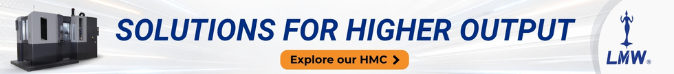
 The design process starts with the simultaneous design of engine ports, water jacket and combustion chamber. Let’s consider each design step one by one and talk about the value that upfront simulation can bring in the design process.
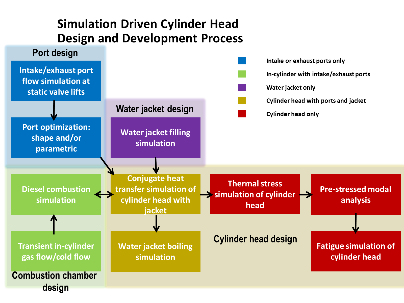
Ports, especially intake ports, are designed for optimum swirl without compromising on pressure drop. In a simulation driven product development process engineers start with a parametric CAD model that they want to optimize that can be read in the ANSYS Workbench ICE system – a semi-automated tool for IC engine simulations. Next, a design space of computational fluid dynamics (CFD) simulations can be created with CAD input parameters, valve lift and back pressure. Using the design exploration function within Workbench, the design space can be analyzed for sensitivity of different parameters as well as response of a given output parameter, swirl for example, to given input parameters. Using several goal-driven optimization schemes, an ideal design can be reached that shows the most optimum behaviour.
 Water jackets are designed for optimum cooling and to avoid localized hot spots in the head. To increase convective heat transfer it is important that the flow and turbulence levels are enhanced everywhere in the jacket, especially at the exhaust-exhaust bridge which is most susceptible to overheating. The region around gasket holes where the engine block jacket connects to the head jacket is critical. Three types of simulations are typically carried out on a water jacket – single phase flow and turbulence simulation, free surface flow simulation for predicting potential air pockets, and controlled nucleate boiling. ANSYS CFD tools are equipped with robust and accurate models for these aspects specifically designed for water jackets.
In designing the combustion chamber, amongst the several factors that need to be optimized such as injection location and timing, EGR and bowl shape is one key factor – the fire-deck temperature. This temperature directly affects engine performance while depending upon the cooling performance of the jacket and tightly couples the coolant jacket and head body design to the combustion chamber design. Since engine combustion is a highly transient phenomenon, performing combustion simulation along with conjugate heat transfer of head body is prohibitively expensive.
 The simulation driven product development process starts by simulating the combustion chamber with an assumed constant temperature on the firedeck surface. Next, time-averaged heat transfer values on the surface obtained from this simulation are mapped to a steady-state simulation of the head body and jacket. The new steady-state temperature field on the same firedeck surface obtained from this simulation is then used to replace the constant temperature that was assumed during the combustion simulation in the first iteration. The whole process is repeated iteratively until a time-steady thermal field is obtained. The entire process takes 2 to 3 days of simulation time for one operating point on a typical workstation with a few cores. By using high performance computing, this process can be condensed to less than a day, and multiple operating conditions can be simulated to characterize the thermal behaviour of the head.
Once the head body temperature field is determined, this data is mapped to a structural simulation to understand the durability of the head. In ANSYS Workbench, this data transfer is triggered automatically by creating a multiphysics workflow that connects its Fluent and Mechanical solvers in a seamless manner. Once the thermal data is mapped, other constraints and loads like bolt pretention load and transient pressure load, and material non-linearity can be applied on the structural model. The simulation identifies highly localized stress regions where necessary design modifications can be made to avoid unintended design failures.
Another important aspect of head design is ascertaining the life of the head. Heads are subjected to both high frequency pressure fluctuations and low frequency thermal strain fluctuations. The low frequency thermal strain fluctuations are more important of the two for estimating the head’s life. Fatigue simulation codes like n-Code are coupled with the company’s ‘Structural’ within Workbench, which seamlessly transfers stress results from the structural to the fatigue solver. Different load steps are defined to simulate both high and low frequency load fluctuations and using stress-life and strain-life computations, the life of the head can be determined in terms of cycles withstood.
As can be seen, there are significant advantages of driving every step in the cylinder head with simulation, right from the concept stage to the refinement stage. ANSYS allows easy and systematic design of a head using its simulation environment Workbench. This is what we call as simulation driven cylinder head design.
by -Padmesh Mandloi, ANSYS, Inc.


Leave a Reply