

Sensors in combustion engines face unique challenges in hybrid cars.
Story by: Klaus Grambichler, Senior Application Engineer, Infineon Technologies Austria AG

Klaus Grambichler, Senior Application Engineer, Infineon Technologies Austria AG.
Modern crankshaft sensors must differentiate between intentional rotation while the engine is running and random crankshaft movements, such as those caused by vibrations during purely electric driving. This differentiation is the only way, for example, to ensure a smooth transition when switching between the combustion engine and electric motor. And only in this way can components such as the starter and the battery be dimensioned most cost-effectively. In this article, Infineon describes corresponding algorithms in the latest XENSIV™ crankshaft sensor.
Car manufacturers across the globe are expanding their portfolio of drive systems. Even looking beyond the fuel cells and synthetic fuels of tomorrow, there is still a vast number of hybrid options spanning the gap between combustion engines and electric motors. These options range from stop-start combustion engines, where the motor shuts off for a few seconds at a red light and then does a cold start. The plug-in hybrids that can quickly drive 50 kilometres in all-electric mode before the combustion engine kicks in as the battery runs low. It could also be when the vehicle is travelling at high speed on a highway.
Two different implementations of even the most modern stop-start systems have already reached the market. In one instance, the combustion engine starts again as if it had been still for an hour and not driven. The second solution monitors the movement of the engine as it comes to a stop. When the engine starts up, the car already knows the crankshaft position and the cylinder to be fired.
If we look at the different positions where the starter-generator may be attached to the drive shaft or the points where the clutch connects different motors to the drive axle, we quickly see that the combustion crankshaft assembly options are virtually limitless.
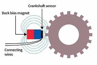
Fig. 1: Diagram of a sensor module
Drive interplay as experienced by the driver
To maximise acceptance of new electric drive systems, manufacturers must win over former combustion enthusiasts with ease of operation and a predictable, smooth driving experience free of “nasty surprises”. A combustion engine can spring smoothly and almost imperceptibly into action – as already experienced at traffic lights or in traffic jams in start-stop mode. Here, the car must know the angle of the crankshaft at all times. If the vehicle stops for three minutes in a traffic jam, the crankshaft sensor can ignore a slight temperature drift or, ideally, compensate for it.
During a 30-minute drive on rough roads with a crankshaft that is free to move when decoupled from traction wheels, however, the sensor could incorrectly count a slight shake or vibration of a tooth or, in the worst case, interpret these movements as a new, valid signal. For a combustion engine can seamlessly slip into action, the sensor mustn’t incorrectly count any of the teeth moving past it. It is imperative that the sensor does not miss any teeth, does not count any
new teeth, and does not mistake the rotational direction.
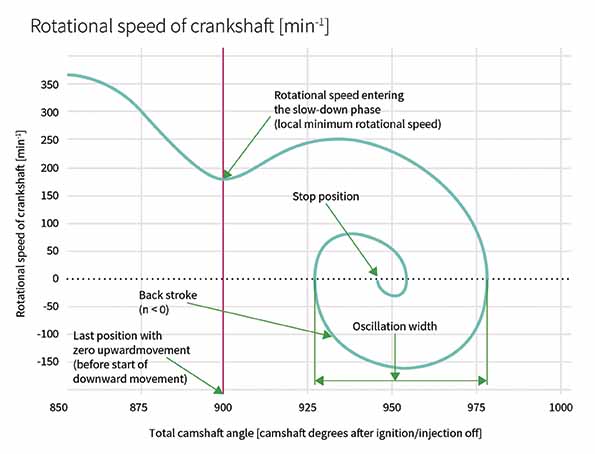
Fig 2: Diagram of a crankshaft coming to rest when the ignition is switched off

Fig 3 : Rotational behaviour of the crankshaft during the direct start
These criteria are broken down inside the crankshaft sensor as there is a magnet inside the sensor housing, and the teeth modulate the field lines of this magnet as they spin past. As such, the fluctuations in magnetic field strengths determine the sensor’s performance. These are dependent on several factors, including the air gap between the sensor, rigger wheel and the temperature. This paper focuses primarily on the mechanical components that are relevant to the sensor’s performance.
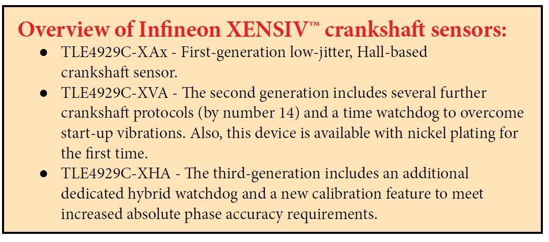
The XENSIV™ TLE4929C crankshaft sensor family from Infineon has various functionalities that help to achieve the goal mentioned above. The third generation of the sensor will come to the market soon. In addition to the already established stop-start algorithm and the algorithm for compensation of vibrations at a standstill, it features an entirely new hybrid algorithm.
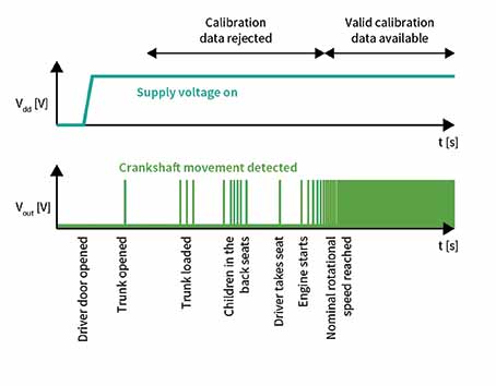
Fig 4: The signal output of the crankshaft sensor when loading the car
The conventional stop-start algorithm
The “smallest” solution for reducing fuel consumption involves switching off the engine. It is already widely deployed and available as a conventional stop-start algorithm. This function can correctly interpret shortstops in congested traffic or at red lights and can compensate for small temperature drifts.
Magnets are subject to substantial temperature drifts, which can change the magnetic field by up to 40 per cent over the given temperature range. In the case of crankshafts with well-fitting bearings, the next most significant factor to impact sensor behaviour is electrical in the source. Number three in the lineup are the changes in the air gap between the trigger wheel on the crankshaft and the sensor module on the engine block.
Ideally, the sensor remains fully calibrated, and when the combustion engine starts again, it can correctly output the position and rotational direction of the crankshaft as soon as the first tooth of the trigger wheel spins past. This functionality is independent of any modifications to the architecture of a combustion engine. All it requires is a slightly larger starter battery and starter motor and alterations to the software in the controller. Figures 2 and 3 show the disengaged crankshaft comes to a stop when the ignition is off. It also shows the quickest possible way to start for an Otto engine when compressed air is still in the cylinder (known as a direct start).
Vibrations while stationary
Modern cars carry out a range of self-diagnostic checks as soon as the driver door opens. These checks reduce the amount of time it takes for a warning lamp to light up. From the moment the car door is opened to the time the car pulls away, there are other possibilities. The vehicle can be loaded, for example. Children are required to buckle up. As such, it is entirely reasonable for the car to rock slightly while stationary. These slight movements travel through the drive wheels, transmission and clutch and cause the crankshaft trigger wheel to turn. In some unfortunate situations, this can result in the crankshaft sensor picking up a valid magnetic signal.
The algorithm in the Infineon sensor deletes calibration data generated before the engine switches on. Suppose we take just a brief look at the full range of hybrid architectures. In that case, it quickly becomes apparent that this add-on function will help car manufacturers to identify and ignore any inaccurate calibration data.
As figure 4 shows, we can draw several conclusions from the sensor’s output signals over time. Firstly, we can see that the activated sensor bars the nominal rotational speed. Consequently, the calibration data gathered up to the time of theoretical rotational speeds can be reset. Secondly, we see that this procedure repeats if the sensor does not identify a tooth for a brief period.
Hybrid algorithm
A new function is quintessential for a plug-in hybrid solution. To correctly identify the position of the crankshaft trigger wheel, an algorithm has been implemented in the sensor that detects slower, sub-nominal crankshaft rotation and, in conjunction with other monitoring functions, prevents incorrect calibrations. New calibration data is only accepted when the system is operating normally.
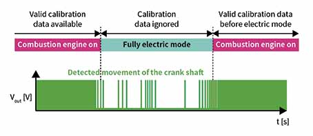
Fig 5 : Signal output of the crankshaft sensor while driving in the hybrid module
This function enables every crankshaft vibration to be captured with the corresponding signals for the forward and backward movement without the crankshaft sensor incorrectly responding to supposed changes to the mechanical setup such as a shift in the air gap or some other mechanical misalignment.
Collectively, the algorithms named here enable the movements of the crankshaft trigger wheel to be accurately observed and tracked. The engine control unit knows at all times which stroke each piston is on and the time before the next ignition (based on the crankshaft angle). If the algorithms are correctly aligned, the system will operate correctly, ensuring that the engine warning light stays off.
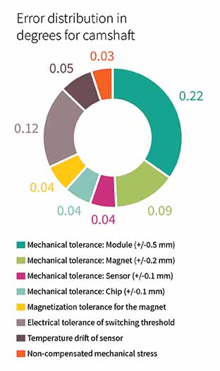
Fig 6: Breakdown of position errors
Improved crankshaft sensor enables other components to last longer.
As the crankshaft sensor always provides reliable information, the sizing of components required to restart the combustion engine can be reduced. The starter generator usually turns the crankshaft for several rotations until the detection of the home position of the crankshaft. The minimum rotational speed over several hundred rotations has been reached.
With an advanced crankshaft sensor, the fuel can be injected and ignited in just half a rotation. Starting the engine in this way requires only a fraction of the battery energy needed for a cold start. Manufacturers can thus choose between a longer service life for the starter and battery, or size down and save costs and weight, which – in turn – translates into a slight drop in consumption. This design also enables a great driving experience as the combustion engine starts quickly and smoothly.
More precise switching points
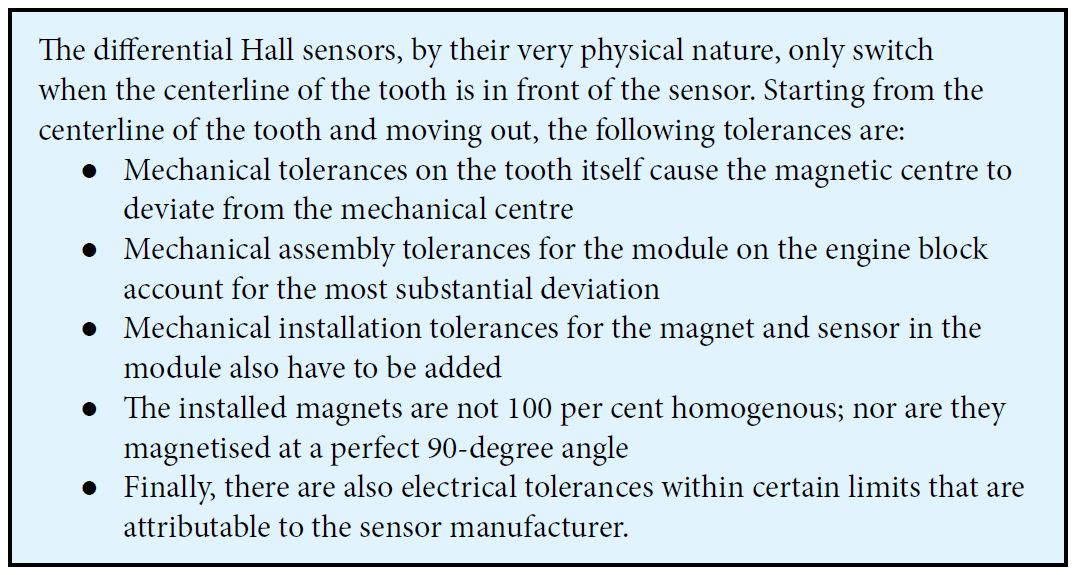 Installed on the camshaft, the XENSIV™ TLE4929C can compensate for production and assembly tolerances on the supplier and manufacturer sides thanks to its programmable switching threshold. This ability means that this position sensor improves angle accuracy both on the camshaft and the crankshaft. Systematic errors are compensated for by the engine control unit and are not included in the above list. They include signal propagation delays, which are already accounted for in the control unit’s timer.
All of the components listed above result in a random error, which at best resolves itself but, at worst, can represent a massive fault. The sensors allow switching thresholds to meet the modern-day requirements. The module manufacturer can do this at relatively low cost by individually calibrating the switching point of the module at the end of the production process. It can also be done on the dry engine itself at a slightly higher cost. The benefit for the car manufacturer here is that the calibration also compensates for their production tolerances. In contrast, the tier 1 supplier can only offset for the module; the OEM’s installation error doesn’t reduce.
Easy calibration procedure
At a mid-point in the switching threshold, suitable systems are used to measure the misalignment between the machining centre of the tooth and the actual electrical edge. After this, the systematic errors are subtracted, and the remaining offset is programed and permanently stored in the sensor as the programmable switching threshold. As shown in figure 6, this method can be used to eliminate nearly all sources of error and improve the overall accuracy from +/-0.6 degree camshaft to +/-0.1 degree camshaft.
Summary
The combustion engine has had its day. From 2020 to 2025, all major car manufacturers worldwide will develop and launch their last hybrid platforms. After this, even the last-generation of development engineers working on combustion engines and possibly also transmissions will have to find a new home in the emerging fields of the fuel cell, battery and electric drive technologies. The combustion engines developed today will be around for several decades to come. As such, it is vital that the technology used in these models is reliable, long-lasting, and up to date. Luckily, the challenges that hybrid engines and, in particular, crankshaft and camshaft sensors face in these systems are already known and being successfully addressed by Infineon. ACI


Leave a Reply