The objective of this article is to present new advanced testing procedures for regenerative braking. The first part of the article introduced the work and presented the methodology – test procedure, instrumentation, post-processing formulae, etc.– for the vehicles whose regenerative system was characterised in terms of durability testing. This second part will focus on performance testing.
Performance Testing
- procedures
Vehicles 3 and 4 are tested in IDIADA HQ Proving Ground. The following test program is considered:
- stopping distance:
Figure 8: Stopping distance procedure
- Auto Motor und Sport (AMS):
Figure 9: AMS procedure
The IBT of all brake discs before the first brake application must be below 100 degrees Celsius. The test is to be performed with the most aggressive driving mode in terms of powertrain (minimum time possible between brake stops).
The test sequence is as follows:
- Accelerate the vehicle to the target speed
- Release the throttle and immediately and rapidly apply the brakes to a pedal effort target of 120 daN
- Immediately after coming to a rest repeat previous points until 10 stops have been achieved. The driver and codriver may notice smoke and smell.
- After the last stop, immediately accelerate the vehicle up to 100 kmph and cool down the brakes until all brake discs have reached a temperature below 100 degrees Celsius.

Figure 10: Example of AMS test
Figure 11: High-speed fade procedure
The IBT of all brake discs before the first brake application must be below 100 degrees Celsius. The test is to be performed with the most aggressive driving mode in terms of powertrain (minimum time possible between brake snubs).
The test sequence is as follows:
- Accelerate the vehicle to the target speed
- Release the throttle and immediately and rapidly apply the brakes pedal to reach 0.5g of deceleration.
- Once 70 kmph is reached, immediately accelerate at WOT.
- Repeat previous points until 9 snubs are completed.
- Once 70 kmph is reached, immediately accelerate at WOT to achieve the target speed. Release the throttle and immediately and rapidly apply the brakes to a pedal effort target of 120 daN until the vehicle is completely stopped.
- After the last stop, immediately accelerate the vehicle up to 100 kmph and cool down the brakes until all brake discs have reached a temperature below 100 degrees Celsius.
- Regenerative braking checks – Low µ
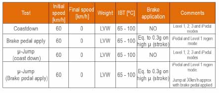
These tests evaluate the different strategies available regarding regenerative braking on a Low µ surface (ceramic surface).
Figure 12: Low µ checks procedure
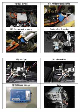
- Instrumentation
Figure 13: Sensors for performance testing
- Blending
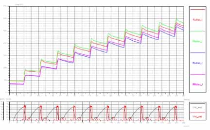
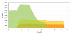
The purpose of this analysis is to characterise the contribution of regen and hydraulic braking when braking.
Figure 14: Blending graph
To do so, the following variables are considered:
- Initial speed
- Deceleration level
- Driving mode
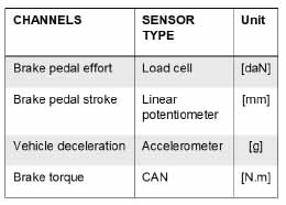
And the channels to be acquired are:
Figure 15: Data acquisition channels
- Advanced regenerative brake characterisation
A more advanced analysis allows analysing strategies of regenerative braking on low-µ surfaces, in different conditions (coast down, pedal apply, jump between different surfaces). Performance is evaluated in terms of
- Wheel lock
- Regen deactivation
- Regen wheel slip control
- Vehicle stability
This is the second article in a four-part series on regenerative braking characterization by Marco Victorero, Test Engineer, Braking Systems in Applus IDIADA.
—————————————————————————————–
With over 25 years of experience and 2,450 engineers specialising in vehicle development, Applus IDIADA is a leading engineering company providing design, testing, engineering, and homologation services to the automotive industry worldwide. Applus IDIADA is in California and Michigan, with further presence in 25 other countries, primarily in Europe and Asia. The article is part of a content-syndication arrangement with the Brake Report.









Leave a Reply