

The concept of integrating powertrain components into a vehicle’s structural framework has been a key engineering approach in motorsports and high-performance vehicles, writes Raunak Dhoot.
Ducati’s trellis frame motorcycles have long employed the engine as a stressed member, eliminating the need for a conventional frame. Similarly, Formula 1 and hybrid endurance racing prototypes use their internal combustion engines as primary load-bearing structures, reducing weight while improving torsional rigidity. With the shift towards Electric Vehicles (EVs), this principle is being re-evaluated, particularly in the context of electric motors and their mounts. This article explores the modal analysis of an electric motor and its mounting structure when used as a stressed member, assessing vibrational characteristics, chassis integration challenges, and how topological optimisation can mitigate NVH (Noise, Vibration, and Harshness) concerns and strengthen the chassis torsionally.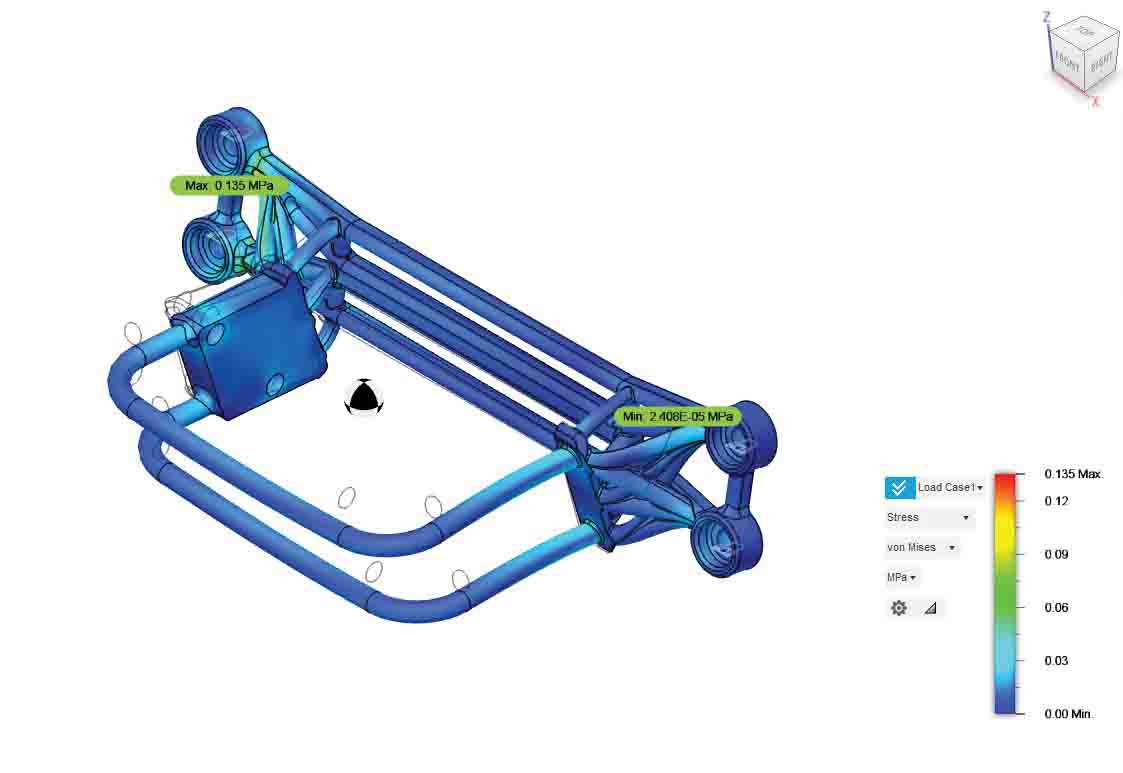
The Role Of The Motor As A Stress Member
Traditional EV architectures rely on a subframe or a dedicated cradle to isolate the motor from the chassis. However, by treating the motor mount as an integral structural component, allowing chassis loads to pass through the motor itself, the vehicle benefits from:
- Enhanced Torsional Stiffness: The integration of the motor into the chassis reduces flex, leading to improved handling precision. Porsche’s 919 Hybrid LMP1 car exemplifies this approach, where the hybrid power unit was an essential load-bearing structure i.n the rear bulkhead
- Reduced Weight: Eliminating an independent mounting cradle or subframe lowers overall mass. Tesla’s structural battery pack follows a similar philosophy by integrating battery cells into the monocoque for added rigidity.
III. Improved Packaging and Aerodynamics: Removing redundant support structures allows for a more compact drivetrain layout, reducing frontal area and improving drag coefficient (Cd) by enabling a more compact rear end, leaving room for aerodynamic devices like diffusers. This is especially relevant in high-performance EVs like the Rimac Nevera, where compact packaging influences aerodynamics.
While these advantages are significant, integrating the motor as a stressed member introduces unique dynamic challenges, particularly with vibration control and stress path mapping.
Modal Analysis: Understanding Vibrational Modes
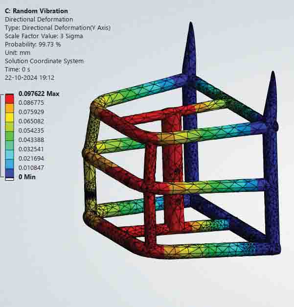
Modal analysis is used to predict how mechanical structures respond to vibrational excitations induced in them via a wide variety of sources, road unevenness, motor jerks and chassis loading and unloading conditions. In a stressed-member motor mount system, various modes of vibration affect both performance and durability.
Key Vibrational Modes In A Motor Mount System
- Torsional Modes: These are critical in vehicles with high torque outputs, such as Formula E race cars, where excessive torsional vibrations can affect driveline efficiency and induce unwanted oscillations and jittering in the chassis.
- Bending Modes: In longitudinally mounted powertrains (e.g., Porsche Taycan), lateral flexion of the chassis due to motor torques can affect rear-end stability, influencing suspension behaviour and in some extreme cases, causing the entire chassis to deform under flexure.
III. Axial Modes: Common in high-revving motors, axial vibrations affect bearing life and can introduce fatigue failures in mounting structures. Rimac engineers counteract this by designing reinforced subframes that mitigate these axial stresses.
- Resonance Frequencies: If the natural frequency of the motor mount system coincides with excitation frequencies (e.g., inverter switching frequencies in high-power EVs), resonance amplification can occur, degrading NVH performance.
Engineers mitigate these issues by conducting computational and experimental modal analysis to avoid these stressed situations, as they might cause fractures in the chassis and can also end up causing multiple accidents due to the unsettled nature of the suspension.
Computational and Experimental Approaches
Finite Element Analysis (FEA)
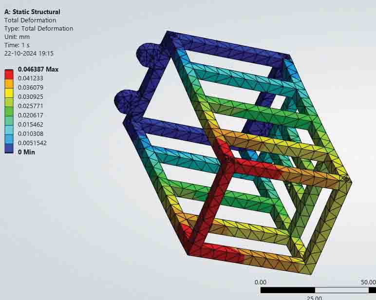
Finite Element Analysis is an indispensable tool in Chassis Design Assessment, allowing engineers to simulate vibrational behaviour and optimise mounting structures before physical prototyping and testing.
- Mesh: The body is split into various infinitesimally small sections, so that analysis can be carried out on any of these sections, and their interaction with the element next to it can be analysed.
- Mesh Refinement: A fine mesh ensures accurate representation of mass distribution and stiffness properties of the bodies and their interaction with one another as well
- Boundary Conditions: Real-world constraints are modelled to simulate chassis connections, torque loads, dynamic forces and the internally generated stresses due to the self-weights of various components
- Material Selection: Advanced materials, such as high-strength aluminium alloys and carbon composites, are evaluated for their stiffness-to-weight advantages. This study can provide validation of material selection and design choices as well, monitoring the stresses generated within is a key aspect of modal simulations.
Experimental Modal Testing
Validating FEA simulations requires real-world testing and, in some cases, destructive testing, commonly performed in motorsports and high-performance EV development.
- Accelerometer-Based Testing: Multi-axis accelerometers and Inertial Measurement sensors, like those used in McLaren’s GT3 programs, measure vibrational responses under real-world loads.
- Laser Doppler Vibrometry (LDV): Used in aerospace and motorsport applications, LDV provides high-resolution displacement data to map modal characteristics with sub-micron precision, by directing a laser beam from the LDV at the surface of interest, and the vibration amplitude and frequency are extracted from the Doppler shift of the reflected laser beam frequency due to the motion of the surface.
- Track and Bench Testing: High-speed testing environments, such as Nardo’s proving ground, help assess how modal behaviour affects vehicle dynamics under high speeds. The Nurburgring Nordschleife is used to dynamically load and unload the frame of the vehicle to ensure stability and structural integrity.
Impact on Chassis Performance
Integrating the motor as a stress member directly affects several aspects of vehicle dynamics and overall performance.
Structural Stiffness
A stressed-member motor mount significantly enhances chassis rigidity. For example, the Mercedes-AMG ONE hypercar utilises an F1-derived stressed power unit, improving lateral stiffness and suspension response. The design of the AMG-ONE was perfected on the Nordschleife, and it presently holds the lap record 6:29.090, taming what is known in the motorsports world as “THE GREEN HELL” with relative ease.
Vibration Damping
Uncontrolled vibrations can lead to fatigue failures in structural components. To address this, manufacturers employ:
- Active Damping Technologies: Systems like Ferrari’s magnetorheological dampers help counteract vibrational harmonics and fluid-filled bushings that mitigate the jittering and suspension hop a stressed chassis creates
- Composite Reinforcements: Koenigsegg uses carbon-fibre mounting structures to provide stiffness while absorbing high-frequency vibrations.
NVH (Noise, Vibration, and Harshness) Considerations
Unwanted vibrations and noise can compromise comfort and performance. Methods to mitigate NVH include:
- Tuned Mass Dampers: BMW’s i8 uses mass dampers to suppress unwanted oscillations in the hybrid drivetrain.
- Adaptive Motor Mounts: Vehicles like the Audi e-tron GT utilise adaptive mounts that change stiffness dynamically based on driving conditions.
Topological Optimisation and Future Innovations
Material and Geometry Optimisation
Using AI-driven generative design tools, engineers optimise stressed motor mounts for mass reduction while maintaining structural integrity. Companies like Bugatti use topology optimisation to create highly efficient, weight-reduced mounting solutions. 3D-Printed Structural Components Additive manufacturing enables intricate lattice structures that enhance stiffness while reducing weight. Porsche’s 3D-printed aluminium suspension mounts provide an example of how topology-optimised components can revolutionise vehicle design.
Active Motor Mounts with Smart Control
Future EVs may incorporate active motor mounts with piezoelectric actuators, dynamically altering stiffness to counteract real-time vibrational inputs. This would allow for adaptable ride and handling characteristics, improving both performance and comfort.
Conclusion
The integration of the motor and its mount as a stress member represents a paradigm shift in performance EV design. Through detailed modal analysis, engineers can fine-tune vibrational characteristics, ensuring optimal stiffness, weight efficiency, and NVH control. This approach echoes previous advancements in motorsport and high-performance vehicles, such as Ducati’s stressed-member engines and F1’s structural power units, showing that structural efficiency leads to superior performance.
With the utilisation of topological optimisation, highly advanced materials, and adaptive damping technology, stressed-member motor mounts will be changing vehicle dynamics to make EVs lighter, stiffer, and more aerodynamically efficient. With the progression of electrification, this fusion may provide new standards for race car and hypercar design, such that future high-performance EVs will be designed for maximum efficiency as well as exhilarating driving dynamics. ACI
————————————————-
The views expressed by the author are his own and do not necessarily reflect the views of ACI Magazine.


Leave a Reply