

Dr Arun Kumar Sampath, Chief Engineer and Head Innovation, Global Technology Centre, Mahindra Electric Mobility Ltd. & Chairman, Branding and Communications Board, SAEINDIA highlights functional safety in ‘Drive by Wire’ vehicles in an in depth article.
Modern vehicles are continuously becoming more complex with vehicle development becoming increasingly challenging since additional and more complex functionalities from different domains are being demanded not only by customers but also by regulators. In the past, the design approach in embedded systems in the automotive industry has been to use mechanical sub-systems with electronic control due to multiple advantages including increased reliability of using electronically supervised systems, faster introduction and implementation of features in vehicles and greater authority of vehicle level functions through more effective digital interfaces between the vehicle sub-systems. Electronic control has been mainly used to control and supervise the functionality and to adapt the behaviour of mechanical systems. In case of an error in electronic control systems, the performance of the mechanical system is reduced while still providing minimum functionality (fail-safe operation). ‘Drive by Wire’ systems (XBW) do not have mechanical systems as backup and in the presence of an error, electronic systems will have to provide minimum functionality and ensure that the errors are confined.
The number of interconnections and interdependencies in the Electrical and Electronic (E/E) systems is rapidly increasing on the functional and hardware level, which in turn leads to an increased vehicle complexity. Engineers continue to face the dual challenges of the need to address increased complexity while simultaneously addressing Functional Safety (FuSa) of the systems in the vehicles. With the advent of drive by wire (XBW) systems in modern vehicles, especially in Electric Vehicles (EVs) with electrified powertrains and accessories, steering, and braking systems, failure of EE components or a faulty decision by an on-board controller can lead to disastrous results and even lead to vehicle crashes and fatalities. The increased complexity and demand for FuSa in EVs demand fundamental reconsideration of established E/E architecture, especially for XBW systems.
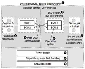
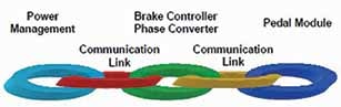
Fig 1. Drive by Wire (XBW) Systems – Generic Architecture (Ref. [1])
Most drive by wire (XBW) systems can be split into two physically separated sections as shown in Fig 1 (Ref. [1]). One section consists of the User Interface (UI) while the other section controls the actuators on the vehicle that are used for steering, braking, suspension and ride control etc. For UI, customers are given the choice through gesture control or voice or haptic feedback, or plain touch screen. The actuators and sensors are controlled and monitored by closely mounted decentralised Electronic Control Units (ECUs). Depending on the level of safety being offered by a specific system in the vehicle, the redundancy of ECUs is determined, especially for safety-critical systems as no single unit can achieve the required failure rates. However, it is important to keep the degree of hardware redundancy minimal to optimise the costs.
In general, two components for one task, in combination with a sufficiently powerful diagnostic and decision unit and a fail-safe behaviour of each component are assumed to be able to achieve the required failure rates. A combination of two or more units is regarded as a Fault Tolerance Unit (FTU). In certain instances, an FTU can also be constructed based on only one ECU if the ECU features a multi-core architecture and an appropriate board design in combination with special mechanisms to allow the execution of multiple safety-critical functions independently on this platform.
An alternate approach to reducing the number of redundant ECUs is to have a network-centric architecture, wherein the distributed network nodes monitor each other. If a single ECU fails, other ECUs react by adapting their mode of operation. Though the number of ECUs is reduced, the complexity of individual ECUs will increase. For example, Brake-by-Wire (BBW) systems typically benefit from a network-centric approach if each brake is set up as an independent unit, which is capable of coordinating with other brakes.
Similar redundancy strategies have to be applied for sensors, on the lines of ECUs, to ensure safe operation. Measurements are required with three sensors simultaneously to allow majority voting among the measurements and thus to detect faults. To reduce Hardware (HW) costs, one or two sensors could be replaced by Software (SW) algorithms.

A vehicle must have proper networking to connect all the electronic components with at least one redundancy including physical separation in the wiring. The overall network has to support a precise timing of messages to ensure that the lost or delayed messages are detected and a maximal roundtrip time is guaranteed. Examples of such networks include TTCAN, TTP/C, FlexRay, and Ethernet in combination with time-triggered extension. The safety-related applications within the network are synchronised using precise data timings to ensure defined latencies which are enabled by operating systems such as modified OSEK, OSEK Time, FTCom, and AUTOSAR.
As a basis for the safe operation of XBW systems, availability of fault-tolerant power supply system is mandatory. Typically, systems with redundancy and mutual isolation are implemented. Certain vehicle architectures are known to implement double redundancy and an additional control unit to configure the power supply in case of failure.
To monitor the overall system, a suitable diagnostic unit or function has to be implemented. These units have to ensure that faults that are occurring are detected such that the remaining system can be reconfigured to maintain sufficiently safe operation. As per regulatory requirements, the system has to tolerate at least one independent fault and still maintain (degraded) performance. Most components of the XBW system already provide local diagnostic functions and provide the output of these functions. Additionally, information can be extracted by network overarching monitoring mechanisms for timings and interfaces. To derive suitable actions from this information, different approaches, mostly relying on heuristics and probabilistic mechanisms, are applied. The challenges for these algorithms are to guarantee short execution times and to provide traceable decisions, which render most Machine Learning (ML) based approaches unsuitable. Typically, the vehicle is regarded as not “self-healing”, wherein restart of
components is considered to heal the system and improve functional safety.
Recent trends in FuSa indicate the need to consider the overall system including the power supply, Battery Management System (BMS), steering system, and a propulsion system capable of accommodating
torque vectoring.

Fig 2. a) BMS Architecture w/o Safety (Ref. [3])

Fig 2. b) Updated Architecture w/ Safety (Ref. [3])
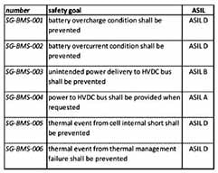
Fig 3. Proposed Safety Goals and ASILs for BMS (Ref. [3])
I. Functional Safety in Battery Management Systems
The ISO 26262 standard establishes a standardised process for Hazard and Analysis and Risk Assessment (HARA), which can be applied to a gamut of automotive systems (Ref. [2]). Recent studies have attempted to illustrate several key steps of an ISO 26262 compliant development process for automotive battery systems and develop a system architecture and functional safety requirements for BMS, elucidate the use of decomposition method to achieve higher ASILs, and to compare alternate BMS architectures against the ISO 26262 standard in order for the system designers to be able to provide multiple options based on FuSa compliance, cost, quality and timeline.
In Figure 2(a), a typical BMS architecture comprising of multiple cells arranged in a series/parallel configuration to achieve the required voltage and traction power to propel an EV is shown. Though such BMS architectures incorporate active or passive cell balancing and the advanced State of Charge (SoC) estimation algorithms to improve charge/discharge efficiency, durability, and extended battery life, they do not incorporate the required FuSa requirements. The updated BMS architecture to reflect the safety goals outlined in Figure 3 is shown in Figure 2(b) wherein the architecture incorporates cell temperature sensors, cell voltage sensors, battery-pack current sensor, serial communication, HV contactor and associated logic to isolate the battery pack from HV DC bus in case of exigencies, to monitor cell internal shorts, and to achieve upgraded SoC estimation.
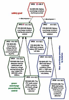
Fig 4. Safety Goal SG-BMS-001 and extension to FSR with decomposition (Ref [3])
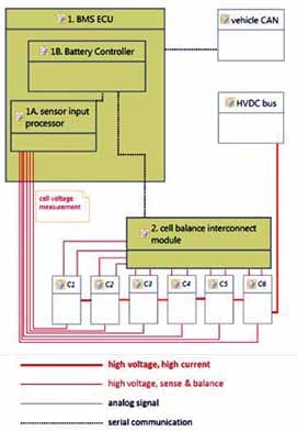
Fig 5. Revised BMS Architecture to meet Safety Goal SG- BMS-001 with Decomposition (Ref [3])
I. a) Proposed Safety Goals for BMS
For an automotive BMS, safety goals are proposed as per Figure 3 with the assumptions that HV contactor, temperature and voltage data of individual cells are available along with battery pack voltage and current data. The HV contactor helps connect or disconnect the battery pack while the current sensor helps determine battery pack SoC; individual cell voltage sensors help determine overcharging or internal shorts and cell balance or imbalance, and temperature sensors help monitor overheating of cells that may lead to thermal runaway of the battery pack.
I. b) FuSa Architecture with Decomposition and ASILs
To meet the safety goal “battery overcharging shall be prevented”, two different concepts can be developed independently. As per the guidelines provided in ISO26262 (Ref. [2]), this goal can be “decomposed” into separate requirements, with major reductions in process rigour of each requirement. The specific safety goal of “battery overcharge prevention” can be achieved through controls enabled in powertrain controller (overcharge prevention through control) and also through self-monitoring mechanism built into the BMS (overcharge prevention through self-isolation). These two mechanisms work independently to meet the same safety goal allowing decomposition into separate requirements as per the ISO26262 framework, part 9, clause 5. The ASIL D requirement in this case can be decomposed into two ASIL B(D) Functional Safety Requirements (FSR), as shown in Fig. 4 (Ref. [3]). The critical benefit of decomposition of ASIL D requirement into ASIL B(D) FSR is the reduced process rigour, which allows nearly all the ISO26262 requirements to be achieved at ASIL (B) level itself. The corresponding BMS architecture is shown in Fig. 5 (Ref. [3]).
In the “Overcharge prevention through Control” mechanism, the BMS would provide battery pack voltage information to the Powertrain Controller (PTC). If the battery pack is fully charged, the PTC would take the battery pack voltage and take decisions not to carry out additional charging of the battery pack which otherwise may lead to the risk of fire or explosion. If the sensed pack voltage itself is not accurate, BMS sends a “signal-not-available” message via CAN to PTC which would, in turn, respond by stopping any battery charging functions in the charger.
In “Overcharge prevention through self-isolation” mechanism, the BMS carries out regular self-monitoring through measurement of cell voltages, cell temperatures, SoC, and pack-level current. If SoC has already reached 100 per cent and if the PTC still tries to overcharge the HV battery pack, the BMS isolates the contactor and protects the battery pack. In advanced contactor management strategy implementations, the contactor may remain closed but the current allowed might be (close to) zero, effectively not charging the battery pack any further.
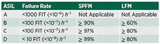
Table 1. ASILs and Failure Rates as per ISO 26262 Standard (Ref [2])

Figure 6. HARA Analysis for Electric Power Steering Ref. [4])
It is important to understand that the decomposition of ISO26262 requirements necessarily requires independence between the decomposed requirements, which in turn demands that there are no common failure modes between the decomposed requirements, which get extended to hardware and software that they do not have common failure modes. The specific design features that may be used to achieve independence of decomposed requirements include the following:
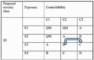
Table 2. New ASIL assignment for ADAS and higher steering rack forces (Ref [4])
Use of separate and distinct sensor designs for the two methods of preventing overcharge, which can be achieved using a battery pack voltage sensor that can
communicate to the PTC through CAN protocol. The cell temperatures and voltages could be processed by BMS alone with independence from PTC.
Independence of data processing with no commonality in Hardware or Software.
Rating for PTC of at least ASIL B in order to perform the function that meets ASIL B(D) FSR. Physical separation of the independent circuits in general such that common cause failures such as EMI EMC, short circuit paths etc. are avoided.
Independent design and manufacturing test procedures for soldered connections, harness
connections etc. to protect against systematic errors in the design of components.
I. c) Functional Safety Hardware Architectural Metrics
In order to meet the ASIL D requirement, ISO26262 defines several Hardware Architectural Metrics (HAM), given as follows:
The Single Point Fault Metric (SPFM), which quantifies the HW architecture’s exposure to single
point failures as a share of total failure rate. The SPFM requirements are 90 per cent, 97 per cent, and
99 per cent for ASIL B, ASIL C, and ASIL D systems, respectively.
The Latent Fault Metric (LFM), which quantifies the HW architecture’s robustness against latent failures as a share of total failure rate. The LFM requirements are 60 per cent, 80 per cent, and 90 per cent for ASIL B, ASIL C, and ASIL D systems, respectively. The Probabilistic Metric for Hardware Failure (PMHF), which quantifies the risk of safety related random HW failure. The PMHF requirements
are < 10^(-8)/hour, < 10^(-7) hour, and < 10^(-7) hour for ASIL B, ASIL C, and ASIL D systems,
respectively.
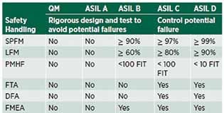
Table 3. Handling of Safety Matrices of ASILs (Ref [2])
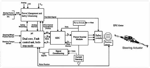
Fig 8. EPS Control path using a dual core microcontroller integrated with power management and safety monitoring (Ref. [4])
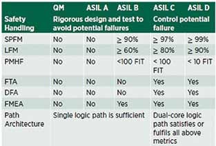
Table 4. Safety and ASIL Target Metrics and Logic Requirements (Ref [4])
The BMS architecture in Figure 6 with decomposition meets lower requirements of ASIL B(D). However, the HAM should be performed at the Safety Goal level before decomposition to comply with ASIL D, ensuring that nearly all HW failures are not Single Point Failures (SPFs) as redundancy is paramount. In the architecture shown in Figure 5, HW or SW errors arising out of BMS board do not lead to SPF as redundancy is established through the safety requirement in PTC by “prevent overcharge by control” requirement, leading to high levels of SPFM. On similar lines, errors through HV contactor weld do not lead to SPF and may not need a redundant contactor in HV battery pack. High levels of LFM need to be achieved through detection and prevention of Latent Failures in the entire system by a) self-diagnosis status of BMS to be communicated to PTC through CAN and b) self-diagnosis status of PTC to be conveyed to BMS through CAN.

Fig 9. Electric Drivetrain HARA Analysis (Ref [5])
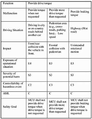
Fig 10. Electric Drivetrain Safety Goals (Ref [5])
II. Functional Safety in Steering Systems
As modern vehicles are moving away from Electro-Hydraulic Power Steering (EHPS) towards Electric Power Steering (EPS) systems, there is an increasing need to design for FuSa requirements of the EPS units consisting of three key elements viz a) power supply unit, b) microcontroller, and c) Gate Driver Unit (GDU). The functional safety of these units is driven by the safety goals and the ASIL determination of the EPS systems. Though the ASIL levels and failure rate metrics as per ISO 26262 Part 5 Section 8.4.5 as shown in Table 1 (Ref [4]) are applicable for Functional Safety in Steering systems also, the use of more Advanced Driver Assistance System (ADAS) application in the EPS and the continuous need for increased torque and better manoeuvrability of vehicles has been posing new challenges for EPS systems in the form of higher forces at the steering rack and increased ADAS functionalities.
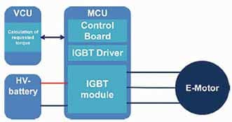
Electric Drivetrain System Architecture a) without and b) with Functional Safety (Ref [5]
This resulted in changes in ASIL computation for the EPS system because any sudden loss of assistance (LOA) may lead to catastrophic accidents. In Figure 6, the steps taken to determine the ASIL of the steering system in the vehicle based on Hazards and Risks (HARA analysis) are shown. The objectives of HARA include a) identification of the hazard events of sudden LOA caused by a malfunction in the steering system and b) formulation of the safety goals with their corresponding ASILs in order to mitigate any hazard event and avoid any unreasonable risk.
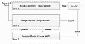
Fig 12. Electric Drivetrain Functional Safety 3-Layer Architecture (Ref [5]
As the definition of controllability in ISO 26262 is not fully mature, a recent study proposed a new metric to relate a range of torque magnitudes to the controllability class C0 – C3 in Table B.6 part 3 of ISO 26262 standard, as shown in Table 2 (Ref [4]), wherein the controllability class has changed from C2 to C3 with ASIL changing from B to C.
As ASIL C accepts up to three per cent of single point failure and 20 per cent of latent failure as shown in Table 3 (Ref [2]), for steering systems with ASIL C levels, a single logic or control system is not adequate to mitigate or reduce any potential risk of sudden LOA. This inherently calls for redundancy for the control and logic gates of the EPS system to ensure high reliability and avoid sudden LOA. Two kinds of redundant systems are applicable for EPS viz, Homogeneous and Heterogeneous. In the case of Homogeneous redundancy, multiple elements of a single type of component are used to achieve redundancy, such as the use of dual ECUs, microcontrollers, sensors, and power supplies for steering motor. It is easier to implement but susceptible to systematic faults. In the case of Heterogeneous redundancy, multiple components of different types are used to achieve redundancy such as steering control using differential brakes. This design is inherently more resistant to systematic faults.
The Functional Safety requirements as per ISO 26262 Part 5 Annex E are applicable to both non-programmable and programmable elements such as Application Specific Integrated Circuits (ASICs), Field Programmable Gate Arrays (FPGAs), and Programmable Logic Devices (PLD). The main Failure in Time (FIT) contributor is the microcontroller with a range of Probabilistic Metric for Hardware Failure (PMHF) 41 per cent to 45 per cent considering The Single Point Fault Metric (SPFM), which is more than the safe allowance of three per cent SPFM for ASIL C as per Table 3. In order to mitigate the potential risk of sudden LOA due to FIT from microcontroller, it is imperative to incorporate redundant logic in EPS system architecture. The Software (SW) redundancy can be achieved using the same processing unit or different processing units, as shown using different architectures in Figure 7 (a) and 7 (b). The aim of the SW redundancy is to detect failure in the processing unit as early as possible by dynamic SW comparison whether using same or different processing units. In the case of failure of primary path, the redundant path is responsible for verifying the primary path’s calculation and taking appropriate actions if a failure is detected. This can be done using separate algorithm designs and code to provide SW diversity. As per the SW redundancy using reciprocal comparison of SW in different processing units shown in Fig. 7 (b), failures are detected as early as possible through exchange and comparison of data in each unit on a real-time basis to detect differences which might cause failure. The SW architecture in Fig 7 (b) allows for HW and SW diversity in addition to processor types (dual or tri-core), separate algorithm designs, code and compilers.
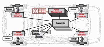
Fig 13. BBW Systems with a) Centralised Redundancy and b) Distributed Redundancy (Ref. [6])
The EPS control path using multicore microcontroller (dual or tri-core) with integrated power supply management, as shown in Fig 8 (Ref [4]), enables an internal self-test and lockstep mode, monitors the microcontroller and controls the safety switch of the EPS motor thus providing a higher level of safety. The Failure in Time (FIT) for this architecture significantly reduces to be in line with ASIL C requirements (PMHF < 100 FIT). This architecture provides high availability and controllability for the EPS systems to decompose ASIL-C determination of EPS in case of LOA. The ASIL target metrics and the logic path architecture of the EPS system are shown in Table 4.
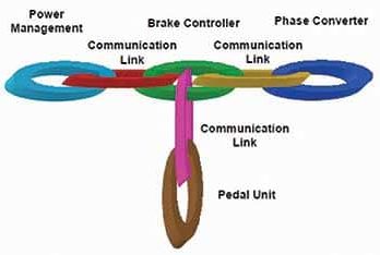
Fig 14. Dependencies of BBW Systems with a) Centralized Redundancy & b) Distributed Redundancy (Ref. [6])
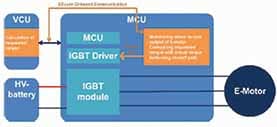
III. Functional Safety in Motor Control Systems
The traction control systems in Electric Vehicles (EVs) have been increasingly using Permanent Magnet Synchronous Motors (PMSM) with high power density and high energy efficiency. Owing to the criticality of motor control systems, high ASILs (Level C and above) are typically assigned to these systems during design and development.
For the basic EV drivetrain architecture shown in Figure 11 (a), a portion of the HARA analysis is captured in Figure 9 wherein the malfunctions, driving situations, and impact on the vehicle and users are elucidated with severity of potential harm as S3 and controllability of hazardous event ranging from C2 to C3, resulting in ASIL C level in each case (Ref [5]).
In Figure 10, the corresponding safety goals are depicted ranging from the Motor Control Unit (MCU) not to provide drive torque when it is not requested (SG 1) to MCU not providing more brake torque than what was requested (SG 4) with all of them having ASIL C requirements.
A three-layer system architecture to capture the Functional Safety requirements for the EV drivetrain is captured in Figure 12 (Ref [5]) wherein Layer 1 (functional level) accounts for Vehicle level management functions, Layer 2 (function monitoring level) recognises the faults in functional SW of Layer 1, and Layer 3 (controller monitoring level) interacts with the function controller and enables HW and SW diagnostics.
The EV drivetrain system architecture with Functional Safety implementation is shown in Figure 11 (b) wherein the system is implemented with a multicore microcontroller which is developed as a safety element out of context (SEOOC), supports up to ASIL D application, and provides two-lock stepped CPUs (core 0 and core 1) and one non-lock-stepped core (core 2). While Layer 1 is assigned to core 0, Layer 2 is assigned to core 1, and Layer 3 periodically checks the microcontroller and monitors the supply voltages to the system for other layers to function properly. Both Layer 2 and Layer 3 offer shutoff with Layer 2 acting as Torque Monitor and Layer 3 providing a redundant shut-off path in case Layer 2 fails (Figure 12).
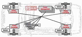
IV. Functional Safety in Brake by Wire Systems – Centralised vs Distributed Redundancy
The traditional centralised redundancy and advanced distributed redundancy Brake by Wire (BBW) architectures are given in Figures 13 (a) and 13 (b), respectively while the corresponding dependencies are given in Figures 14 (a) and 14 (b).
The dependencies in Figure 14 clearly indicate the benefits of 4 vs 3 modules and 3 vs 2 links as we go from Centralised towards Distributed Redundancy.
The traditional centralised redundancy architecture and dependencies in Fig 13 (a) and 14 (a) consist of the following (Ref [6]):
The advanced distributed redundancy architecture and dependencies in Fig 13 (b) and 14 (b) consist of the following (Ref [6]):
An important requirement for effective BBW distributed architecture is the communication protocol that is deterministic, connects and correlates the distributed control units, is fault-tolerant, encapsulates at the protocol and physical level, has compatibility with existing systems, is cost effective, and acts as a true open standard. Existing CAN communication protocols are not suitable for developing fault tolerant safety critical BBW applications because they are not deterministic, with unpredictability of the timing of messages. Multiple organisations and consortiums have been working on Time Triggered Protocol (TTP) CAN architectures with TTP/C and TTP/A being two real-time protocols of the Time-Triggered Architecture (TTA). The TTA offers high-bandwidth, scalable and fault-tolerant communication with the safety-related features of pure time-triggered communication and the flexibility to support event-triggered communication for other applications. TTP/C focuses on the interconnection of components in order to form a highly dependable real-time system suitable for safety-critical XBW systems. TTP/A supports modular design, provides easy and economical integration and management of sensors and actuators into a network, and can be implemented on low-cost microcontrollers.
It is important for a BBW architecture to have fault-tolerant safety strategies built on inherent system redundancy and with deterministic communication systems connecting and encapsulating the distributed sub-systems from each other. Figures 15 a) and 15 b) depicting distributed star topology and unidirectional redundant ring structure, respectively, ensure that encapsulation is performed in the time domain and additionally to some extent in the value domain. The distributed star topology shown in Fig 15 a) suffers from inherent weakness of single point failure though it offers redundant bus-guardians and encapsulated sub-systems. The distributed ring architecture shown in Fig 15 b) offers very high robustness against local, mechanical or electrical failures. Unidirectional wires can be routed separately, such that a loss of any single connection and many combinations of multiple cuts do not cause any loss of information.
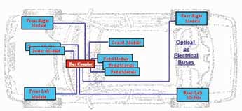
Fig 15. a) Distributed Star Topology (Ref. [6])
The distributed BBW architecture as implemented in a vehicle is shown in Figure 16 wherein multiple displacement sensors and force sensors areconnected to the wheel nodes to capture driver intent. Each wheel node calculates the actuation commands for all four wheels. These commands are communicated via the network so each of the four-wheel nodes can compare their own actuation commands with those calculated by the other wheel nodes. The voting mechanism in the network layer of each wheel node can then disable the power to individual actuators in case of a fault. If a node needs to be shut down the brake force is redistributed to prevent the vehicle from yawing.
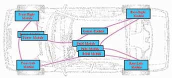
Fig 15. b) Unidirectional Redundant Ring Structure (Ref. [6])
The advanced brake functions are executed in the two front-wheel nodes. If the front wheel nodes do not calculate the same output commands for these advanced brake functions, the function will be deactivated. This provides fail-safe operation. The dependable power supply is provided by two 42V batteries. Each battery is connected to a distribution box that protects the 42V net from short circuits. Each wheel node is connected to each distribution box providing redundant power supply. The communication system is itself failure tolerant. The computation and control are distributed to the available resources that verify against each other over the network with appropriate network support. Value domain encapsulation using a mutual distributed exclusion protocol feature is one further measure to allow detection of failures in the value domain across the network and without further software interaction. The communication protocol allows the incoming datasets to be compared against a reference dataset provided by the attached host and to determine the majority agreement within the network. In case of failure of one ECU that cannot detect its own faultiness, this network feature allows to prevent the commanding of actuation with data from such faulty nodes.

Futuristic instrument panel of vehicle.
Summary
FuSa in automotive systems as per ISO 26262 standard is an increasingly necessary requirement due to higher levels of features and associated HW and SW architecture complexity in vehicles. Though ISO 26262 standard is a generalised document to ensure FuSa, it needs to be interpreted appropriately for specific systems such as BMS, steering systems, drivetrain, brakes etc. As FuSa standards evolved from IEC 61508 towards ISO 26262, avoiding SPFs through structured analysis and safety mechanisms is still the underlying design philosophy. To achieve ASIL D level compliance, decomposition into independent and redundant ASIL B(D) systems is a crucial tool to avoid all types of errors. The SPFM is almost 100 per cent because no random failures lead directly to violation of a safety goal. For FuSa applications on BMS, high levels of LFM are achieved through fault detection and communication through CAN between systems such as BMS and PTC. The HAM should be performed at the Safety Goal level before decomposition to comply with ASIL D.
The use of more ADAS application in the EPS and the continuous need for increased torque and better manoeuvrability of vehicles has been posing new challenges for Electric Power Steering (EPS) systems in the form of higher forces at the steering rack and increased ADAS functionalities. Recent trends indicate design of highly available EPS system architecture with FIT significantly reduced to be in line with ASIL C requirements (PMHF < 100 FIT) using control logic paths utilising redundancy concepts. ASIL C mitigation was achieved by incorporating a dual-core microcontroller integrated with a power management and safety monitoring unit thus providing high availability and controllability for the EPS systems to decompose ASIL-C determination in case of LOA of steering systems.
As more and more OEMs demand their suppliers to provide drivetrain control systems adhering to ISO 26262 standard, innovative technical solutions employing multi-layer FuSa system architecture employing multicore microcontroller (developed as a safety element out of context (SEOOC)) are being pursued meeting ASIL C and higher requirements. The different layers of FuSa simultaneously address multiple ASIL C safety goals while also providing redundant shut-off paths in case a layer fails.
The distributed BBW architecture is the recent trend with multiple displacement sensors and force sensors connected to the wheel nodes, with each wheel node calculating the actuation commands for all four wheels. The fail-safe operation is provided by constantly checking if the specific wheel nodes do not calculate the same output commands for these advanced brake functions. Each wheel node is connected to each distribution box providing redundant power supply through the use of two 42V batteries that are protected from short circuits. The communication system itself is failure tolerant with the computation and control distributed to the available resources that verify against each other over the network.
In automotive systems with growing complexity, all safety goals must be satisfied simultaneously with associated ASIL levels in a single implementation by detecting and addressing systematic errors in advance through a higher of independence of systems. It is to realise decomposition to lower levels, which will continue to be a challenge to design ISO 26262 compliant systems.
[1] Reference: Peter Johannes Bergmiller, “Towards Functional Safety in Drive by Wire Vehicles” https://link.sppringer.com/book/10.1007/978-3-319-17485-3
[2] Reference: International Standards, “ISO 26262 Functional of Safety for Road Vehicles, Parts 3, 4, 5,” Geneva, Switzerland, Second Edition 2018.
[3] Reference: William Taylor and Jody J, Nelson, “High-Voltage Battery System Concepts for ISO26262 Compliance” SAE Paper 2013-01-0181 https://www.sae.org/publications/technical-papers/content/2013-01-0181
[4] Reference: Saif Salih and Richard Olawoyin, “Computation of Safety Architecture for Electric Power Steering System and Compliance with ISO26262” SAE Paper 2020-01-0649 https://www.sae.org/publications/technical-papers/content/2020-01-0649
[5] Reference: Zhihong Wu, et. al, , “Functional Safety and Secure CAN in Motor Control System Design for Electric Vehicles” SAE Paper 2017-01-1255 https://www.sae.org/publications/technical-papers/content/2017-01-1255
[6] Reference: Nico A. Kelling and Worthy Heck, “The BRAKE Project – Centralized vs Distributed Redundancy for Brake-by-Wire Systems” SAE Paper 2002-01-0266 https://www.sae.org/publications/technical-papers/content/2002-01-0266 ACI
——————————————————————
The expert views and opinions of the author are his personal opinions and do not necessarily reflect the views of the ACI magazine.